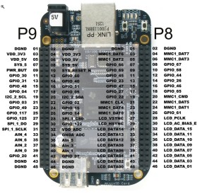
Greetings and welcome to the forums! I use Pin GPIO 7 for PTT and GPIO 30 for COS (Optional). The software vox in the 1.0.0 Beta 1 is a little spotty right now it might take some hacking to make it work right now, so the COS is currently the best option.
If you are looking at the Getting Started Hardware Guide then what is labeled as Pin 12 / GPIO 18 will go to GPIO 7 on the BBB (Pin 42 on the P9 Header) and your ground can go to any of the DGRD pins on the BBB. If you want to use the COS use GPIO 30 on the BBB (Pin 11 on the P9 Header). This will be active when pulled to ground. It uses an internal pull up resister to pull it high when it is opened.
Make sure that your pins are set properly in the Ports tab in the Web Interface, then rebuild the config after saving. You will need to restart the device so that the startup script can initialize the pins with the OS.
Hope this is of help. Thanks.
73,
Aaron – N3MBH / WRFV871
OpenRepeater is offered free of charge. Find out how you can support us.
Author
Posts
Viewing 1 post (of 1 total)
The topic ‘BeagleBone Black Header PinOut’ is closed to new replies.
 .
.