
- This topic has 8 replies, 2 voices, and was last updated 9 years, 11 months ago by
 Aaron, N3MBH.
-
AuthorPosts
-
April 16, 2016 at 10:01 am #1806
 Aaron, N3MBHForum Administrator
Glad it is working for you. Not a problem, hopefully we will improve our documentation as we go. The knowledge base was recently implemented, and I have yet to write up an article explaining this in a clear cut manner.
So I looked at your link and you want to use what is referred to on that page as “BCM” pins. UART/SPI/I2C etc are different interfaces than GPIO. Don’t use the header pin numbers, go by the GPIO or BCM number when entering the number into ORP. The GPIO numbers are specific to the processors/boards. On the Raspberry Pi they do a pretty good job keeping the pinouts the same from model to model, but if you look at a clone type board like the Odroid C1, you will see that it uses the same style 40 pin header, but the GPIO numbers differ because of a different processor and board design. In the case of the Raspberry Pi the BCM I think is an acronym for Broadcom (the processor on the Pi).
So for example, if you use pin 15 on the Raspberry Pi header for your PTT control, you will notice that is say BCM 22 or GPIO 22 on the pinout diagram. In your port settings you would just enter “22” for your TX or PTT pin number. The ORP software will take care of the rest (setting up the pin and setting it up as an input or output pin).
For your COS/RX pin that is currently setup to be active low, in other words when you ground that pin it tells ORP that the squelch is open. This is best interfaced using a optocoupler to protect the GPIO pin. See our basic diagram for that on the hardware page. Make sure that you include a pull up resistor to pull the pin up to 3.3 volts when not grounded so that the pin value doesn’t float triggering false COS results.
Hope that helps.
73,
Aaron – N3MBH / WRFV871OpenRepeater is offered free of charge. Find out how you can support us.
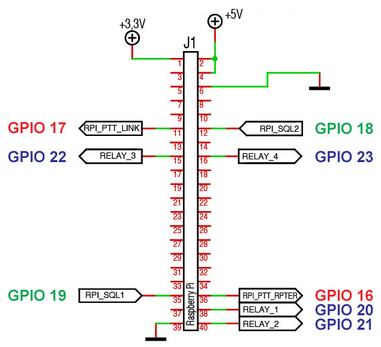
April 16, 2016 at 12:44 pm #1816Aaron, N3MBHForum AdministratorHere’s a mockup of the GPIO header I am working on for some documentation. Hope this makes more sense.
 73,
73,
Aaron – N3MBH / WRFV871OpenRepeater is offered free of charge. Find out how you can support us.
April 17, 2016 at 1:23 am #1817Aaron-
Great explanation! Here’s the GPIO card that came with my RPi kit.
If I use the Easy Digi to interface with the radios, do I need to build a pull up resistor? For my POC, I’m using 2 Boefeng HT’s. Here’s an image of the way I “think” this goes together. Is this correct?
The rest of my parts arrived today! I should have enough to get my system running once I solder everything up!
Thanks again, Aaron!
April 18, 2016 at 7:23 pm #1822Aaron, N3MBHForum AdministratorYes that appears to be correct less the COS circuit. You would need to have a separate optocoupler to handle that and modify the radio to pull a COS line. There are probably some instructions online on how to do that for the Baofengs.
One thing to keep in mind with the Baofengs (or any handheld or mobile for that matter) is don’t expect to be able to do same band repeat without a some serious filters/duplexers because of desense. You would be better off probably doing a one-way crossband repeater and separating the antennas or using a diplexer/duplexer to feed both radios into one antenna. This will at least give you some band separation as well as affordable and compact filtering.
Hope that helps.
73,
Aaron – N3MBH / WRFV871OpenRepeater is offered free of charge. Find out how you can support us.
April 20, 2016 at 8:49 pm #1826Aaron-
Well I finally received all the parts and soldered up as per my diagram above. I do have an issue with the Tx1 being stuck in transmit. Any ideas on where to start troubleshooting that? I’m not sure if I have an error in my assembly or with the software configuration. Any guidance would be great. It’d be nice if you had a “Buy Service” button that started a Webex with ya!
🙂Thanks as always.
April 22, 2016 at 7:15 am #1827Aaron, N3MBHForum AdministratorFirst thing I would check is to make sure that you are not using the VOX mode for RX as this is really buggy and could cause this. Also I would watch the log file as this should give you some indication as to what is happing. It’s easier to do this via SSH: https://openrepeater.com/knowledgebase/topic/watching-the-svxlink-log-real-time
I would also try to isolate the hardware and software and test individually. I would use a basic push button setup for the RX pin and an LED on the TX side to make sure that software and pins are functioning as expected. For the rx, it is set to be active low. There are plenty of push button diagrams out there for the PI for a push button with a pull up resister. Or you can jump them RX pin to +3.3v to keep it inactive and to ground to make it active.
It could be a wiring issue to your radio also. You can simulate the PTT line by connecting it to the 3.3v pin which should put it into TX and when you disconnect it should stop. That will ensure that you wiring is correct.
Hope that helps.
73,
Aaron – N3MBH / WRFV871OpenRepeater is offered free of charge. Find out how you can support us.
April 23, 2016 at 9:06 am #1830Great advice as usual, Aaron.
So it appears that my Tx side is fine (well after using the proper GPIO pin), and my issue is actually on the Rx side. The squelch is always OPEN, therefore the Tx was always on. On VOX, if I push the mute button on my soundcard, the squelch will close and the Tx will turn off. It only transmits when the ID interval arrives.
I also noticed there is a very loud hum, like when plugging cable into an amplifier before the cable is inserted completely. That noise I suspect is keeping the squelch open. So it looks like I have two tasks remaining:1. Identify the cause of the hum.
2. Figure out the COS/optocoupler stuff for a Baofeng/Kenwood radio.Off to the google, but do welcome any advice on either item.
Thanks as always!
April 24, 2016 at 9:39 am #1831Aaron, N3MBHForum AdministratorThe cause of the hum is probably caused by your TX radio. It is either desensing your receiver or causing RFI on your audio lines. Proper shielding and filtering is a must. That is why same band repeat without duplexers is almost impossible.
73,
Aaron – N3MBH / WRFV871OpenRepeater is offered free of charge. Find out how you can support us.
-
AuthorPosts


- The forum ‘Hardware’ is closed to new topics and replies.