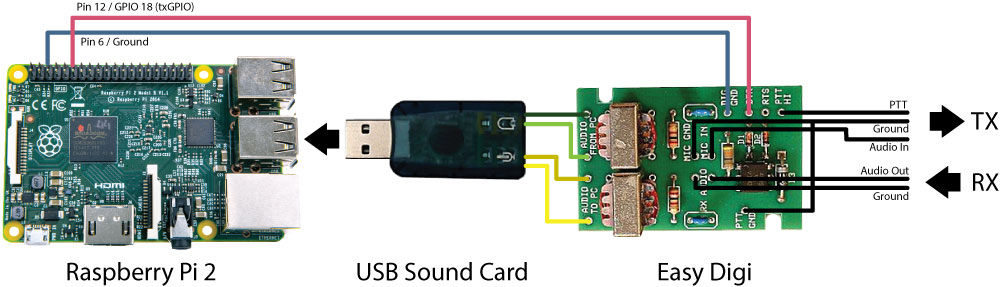
You will need some basic interface circuitry to be able to interface the RX and TX radios to the SBC. If you aren’t looking to build an interface from scratch and are looking for something basic, an Easy Digi and USB sound card should do the trick. Above is a basic diagram of how this should be wired.
Not shown above would be any additional circuitry such as any attenuation resistors to get the audio at the right level and optionally another optocoupler circuit to handle the COS control as the software VOX is a little sketchy right now and is not an ideal solution anyways. Below is an example of what the COS circuit would look like with an optocoupler in a pull up configuration. VCC should go to 3.3 volt pin (NOT 5 volt pin as you could damage your GPIO pin). Ground should go to GPIO ground pin. Input pin will go to the GPIO pin that you assigned to the COS in the web control panel. You will need to provide the appropriate circuitry on the LED side for your needs. Note that The GPIO pin number is different than the actual pin number on the header. 10K should be a good value for the resister.