

 Greetings OpenRepeater users! My name is Juan Hagen! I am amateur radio operator F8ASB and I am new to the OpenRepeater Team and glad to be a part of such an exciting project. I am located in North East France and have been an amateur radio operator since 1996. The radio is a great way to learn in all areas. I maintain 2 repeater in my area: F1ZBV and F1ZBU. The F1ZBV repeater is an analog repeater with running SVXLink on a Raspberry Pi. The OpenRepeater Project is great as it builds upon the concept of SVXLink running on single board computers, but makes it much more accessible.
If you want to find out more about what I am up to personally, feel free to check out my blog at F8ASB.COM (written in French). It covers many of my achievements and projects including electronic boards, CNC machining, and amateur radio activity since 2013.
My role on the OpenRepeater team is to head up hardware design. It is our goal to make a simple but powerful interface to mate the single board computers, like the Raspberry Pi 2, with the radios. I am excite to share with you some of my work. This draws upon my previous board designs, but for the first time integrates sound and SMD components.
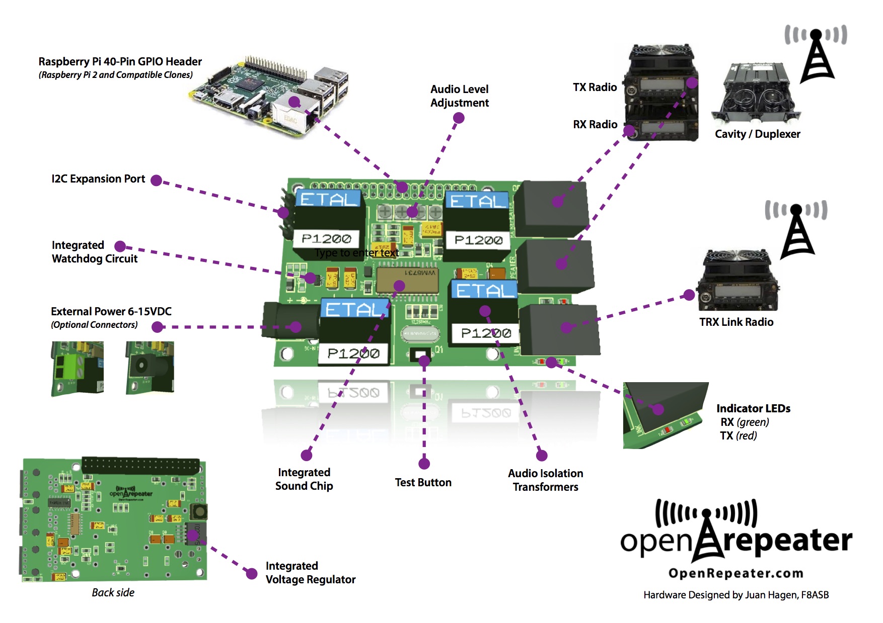
This board is designed to mount on top of the 40-Pin GPIO Header of the Raspberry Pi 2. It should also be compatible with Raspberry Pi clones with the same header and form factor such as the Odroid C1 and C1+ as well as others.
The interface provides radio connections for the primary receiver and transmitter as well as an additional port for a link radio. We have also integrated a sound chip on to the board that works via the GPIO header, so no USB sound card is required with this interface. Isolation transformers are included for each channel to isolate radio audio from onboard sound. Audio level adjustment pots are available to match the radio audio requirements.
We have integrated a voltage regulator circuit that powers the interface board and single-board computer via the GPIO connection. This allows for powering the OpenRepeater controller from 6 to 15 volts DC so that the controller can be powered from the same power supply as most radios.
An I2C expansion port is also provided which will allow for connection of other items such as a Real Time Clock (RTC) or an LCD / OLED display. We initially considered including the RTC on the interface, but not everyone will require it as some setups will have reliable internet connection allowing for automatic synchronization with a time server. Additionally, we have added support to the software for connecting a GPS receiver which can also synchronize system time.
Since a system like this is rather complex, there is a chance that the system could lock up. To combat this, we have added a hardware watchdog circuit that will initiate a reboot if a frozen system is detected.
Other features of the board include indicator LEDs for each port, Green LED for RX and Red for TX. There is also a test button to simulate an open squelch condition. The PCB has the option for use of a DC barrel connector or screw terminal connector as well as options for RJ12 radio connections or inline headers.
Board Features
- Same size and form factor as Raspberry Pi 2 family with mounting holes in same location. Designed to stack on top of RPI2 and exact clones.
- 40-pin RPI GPIO header (Raspberry Pi 2 and clones)
- Radio connections for Primary RX, Primary TX, and Link Radio (TRX)
- Integrated sound chip that works via the GPIO header (not USB sound)
- Audio isolation transformers to isolate radio audio from integrated sound
- Audio level adjustment pots to match radio requirements.
- Integrated voltage regulator circuit that powers interface and single-board computer via GPIO connection. Allows for powering OpenRepeater controller from 6-15 VDC
- I2C expansion port which will allow for connection of other items such as a Real Time Clock (RTC) or an LCD / OLED display.
- Integrated hardware watchdog circuit that will initiate a reboot if a frozen system is detected
- Indicator LEDs for each port, Green LED for RX (COS Line from Radio) and Red for TX (PTT for Radio)
- Test button to simulate open squelch condition
- PCB has option for DC barrel connector or screw terminal connector
- PCB has option for RJ12 radio connection or inline headers.
We are working to make some prototypes of the board to test and integrate with the software. The exact time frame we plan to have this available to the public is still undetermined at this time. To keep up with our progress be sure to follow us on social media by following the links at the top and bottom of the page, as well as joining our mailing list. Things are getting exciting around here, so you will want to stay in the loop.
73,
Juan, F8ASB
That is too cool.. When can I buy one?
Stay tuned Richard. We are working on making a prototype run to do testing with. We don’t have an exact date just yet. Please make sure that you’re on the mailing list as we will announce it there. Thanks.
I too would be interested in a board – we have a need to add external controller for our Yaesu DR-1XE. 73 Paul G6MNJ
Greetings Paul, I just added a Waiting List form to the page if you’d like to sign up.
Please keep me informed
Just added a waiting list form to the page. We will also update via the regular mailing list and social media also.
G6MNJ -> example DR1 and external controller :
https://translate.google.com/translate?sl=fr&tl=en&js=y&prev=_t&hl=fr&ie=UTF-8&u=http%3A%2F%2Fblog.f8asb.com%2F%3Fp%3D1299&edit-text=&act=url
Glad we have joined this project!
With our radioclub in Belgium we would like to delve into the possibilities of replacing our repeater-controller with a low cost SBC, in our case it will be a RPi 2 so the OR image will suit.
Unfortunately, as a non-developper my contribution will only be a feedback on testing the interface board and the SVXlink software. We have smoothly installed the latest beta yesterday and the Pi is waiting for VHF/UHF equipment to interface.
Looking forward for the release of the custom build Easy Digi … we are on the mailing list.
73s de ON3ZOE,
Wim
Hope that we can have a working prototype soon. Would love to be the very first one in my country to test this. Good Luck!
Why 40 pin? Why not 20-pin so it is backwards compatable with all raspberry pis?
Greetings. In earlier testing last year the earlier generation Raspberry Pis with the 700Mhz Processor and 512 MB ram seemed to have problems keeping up. This includes the RPI Model B and B+ as they have the same processor. Given that the A and A+ are a no go also as they have half the ram. The older RPIs just don’t have the horse power required. The Raspberry Pi 2 has a quad core processor and twice the memory, so it is a big step up. Based on that, we have to draw a line in the sand and move forward from there with the way the SBC market is moving. All the pinouts have been set in the 26-pin regions, so you could in theory use it on an older RPI, but that would probably be with unfavorable results. Plus we don’t offer an IMG for single core RPIs. Thanks for your Interest.
Distributor here in the Philippines? I’m interested to be a distributor.
Just be sure to join the waiting list so we can keep you updated.
Has the code been written to support such a daughter board? Does a schematic for the board exist? Is this something we could build ourselves for alpha/beta testing until a production version of the board becomes available? Will this setup allow for connections to echolink or allstar or irlp. I am really jazzed about this project and would love to become envolved in any way I can.
Hi David,
Sorry it took me a few days to moderate and reply to your comment. Yes we are working to implement the drivers for the audio codec chip into the system build in our next beta release. We are working on some prototypes now. Once everything is hashed out with schematics we will make those available to those capable of building their own. There is a proto board with that chip on it which can be found here: http://www.mikroe.com/add-on-boards/audio-voice/audio-codec-proto/. If you are interested in helping out, please fill out our contributor form. Thanks for your support of the project.
Oh…and yes Echolink is supported by the project currently.
GM to everyone,
Is there some news about the interface our friend Juan Hagen has made ? We are looking forward to it as our Raspberry Pi 2 is ready to take the surface mount board and interface with our radios in the repeater shack.
73s de on3zoe.
Greetings,
We are still working on the prototype. Last I heard, they were having some driver issues with the chosen chipset. I believe they were looking for some work arounds or an alternative chip. We appreciate your enthusiasm and support for the project!
This is just what I was looking for. Please keep me informed.
Greetings. Thank for your interest in the project. As long you are on the mailing list or following us on social media, your should be good to get updates. That is usually how we send out our updates. Also being on the hardware waiting list is a good idea too. We will probably release a larger board without integrated sound before this one. Hope to have some more news on this soon. Thanks.
The new PiZero should add a new dimension to this project. Interested in knowing more about interfacing the two together.
The PiZero appears to be underpowered compared the Pi2. Looks like it has a single core processor like the original Pi that is overclocked. It also has half the amount of ram as the Pi2. Another disadvantage is that is doesn’t have an integrated NIC. Not ruling it out yet, just saying it is not our main focus at the moment. Perhaps later on as things progress. Right now out of the Raspberry Pi lineup, the Pi2 is the best contender and what we are focusing on. Thanks for your interest in the project!
Of course the processor clock speed and memory do match that of my Beaglebone Black and that can handle ORP with no problems. I guess we will see.
Is this project affiliated with another project called “Open Repeater Project” at openrepeater.org? Or is it the same project? I see no links together from them, but both websites have pictures of Raspberry Pi. The Goals page of the openrepeater.org (openrepeaterproject.com) seems to be pretty vague. So are these two websites the same project, or different?
Hi Joseph,
No the other project you are referring to is Copy-Cat project. If you take a look at the whois on our domain and on his domains you will see that our project has been around for a year longer. I have made Mr. Myers aware of the name infringement and suggested he join our project for one unified project or change his name to avoid confusion. Unfortunately as of to date, he has not done either. At this point his project appears to have no active development going on. We are preparing to make our second code release any day now. Have a Very Merry Christmas. 73 ~ Aaron (N3MBH)
Thanks for your answer. I am very far away from setting up a repeater, but I am interested in learning all of this stuff. Does this software have the capability to connect to IRLP? And does it have capabilities of autopatch?
Hope you have a Merry Christmas (and Happy New Year) Aaron, and 73 to
Not a problem Joseph. It doesn’t currently support IRLP. We have been talking about adding it in the future. We have to do some testing to see if it would be easily achievable and it may require some hardware as well. It does currently support Echolink.
As for autopatch, that isn’t really too high on the priority list as that is a dying function.
I understand about autopatch. I would just like it (that is, if and when I had a repeater, which would be far into the future…) in case of emergency and there was nobody on the repeater.
I wonder if there could be some sort of external solution to connect the Open Repeater to an IRLP node.
Anyway, thank you for your help on this issue, and someday (someday…) I would like to try to make a repeater. But that would be in a long time.
73 to you, Aaron.
KM4PSL
No problem Joseph. Well we plan to make incremental improvements as we go. It’s more about building a solid core first. Even if you are going to be some time out. You can always pick up a RPI2 or BBB and tinker with the ORP software. Some minimal components a a breadboard and you can simulate the COS and PTT circuits for testing. It will help with learning.
I don’t have a RPi 2, but I’ll look into getting one of those and a breadboard. Not a programmer (only a little VB.NET, HTML, and CSS) but I think I could do a little editing of SVXLink with TCL (which sounds fairly simple, and kind of similar to Batch.)
I assume OpenRepeater is written in C, C++ and/or C#, which I am clueless at. (I learned VB.NET at first, and whenever a try to learn a new language, the capitalization of the commands throws me off.)
Also, before I build a repeater, I would like to try to build a cross-band repeater (which I think would be easier.) Is there a program which would run on a computer to control one of those (that is fairly simple?)
Thank you for your help.
OpenRepeater has a “front end” application that is written in PHP & JavaScrip / Jquery. It stores it’s settings in a SQLite Database. Upon rebuilding the server the database is queried and some PHP scripts are run that rebuild a couple config files for the SVXLink core ad some shell commands are issued manage restarting SVXLink and registering the needed GPIO pins. You could certainly build a one-way cross band repeater. It just comes down to your radios. This is what I would probably recommend for portable setup as you can get around the frequency separation issues that plague a normal repeater. You would just have to use dual band radios to access the repeater and it wouldn’t be an ideal permeant solution.
For additional help it would probably be best to join the forums instead of having an on going discussion in the comments section. Thanks.
This will make it easy for non Linux or computer savy Hams to get a glimpse of what they can achieve and hopefully get them from the old ways and into the new way of enjoying the art of radio.
Thanks Jose. Yes, that is our goal to make the project progressively more user friendly where they less experienced user doesn’t have to worry about what is under the hood. Just download, burn, and go.
Info on other capabilities the team may consider.I am working to build a RaspPi2 controller for the tool shed where my present repeater runs, because I want to add a commercially-available accessory board which has an a/d circuit with 1-of-8 switchable inputs for telemetry and control. I have to control up to 4 existing solar panels which charge 3 heavy-duty 12vdc batteries, and since I am in the mountains, I have to also be able to switch in an a.c. charger when no sun is available, or snow covers the panels.
Hello Joseph,
I see that you signed up for the waiting list. Juan has been working on a larger board that has relay support. This will probably be made available first, then he will focus on the smaller board with integrated sound. You can see his functing prototype here: https://www.youtube.com/watch?v=HMhOBcN50yM
This is currently built with SVXLink Only. We would need to add this into a future ORP build for the relays to work or you would need to hack your own install. Since you are on the list, I will send out updates as soon as he has something to sell. Might be in kit form.
Hi All,
Does the board and IMG support CTCSS (PL) and COS? We have two repeaters that we are able to turn on and off the CTCSS (PL). The current system has an input for CTCSS and COS.
Thanks.
CTCSS is supported by SVXLink but is not fully tested with the current release (1.1.0) and it is currently recommended to use the radios to handle the CTCSS encoding and decoding if at all possible.
For better response, please post these type of questions in the support forum. Thanks.
Okay, I’ve been waiting a year for this board. We have been running an ID-O-Matic IV on our repeater, but we’re wanting something more robust that is driven by the RPi.
How about an update?? The Atlanta Rabbits Amateur Radio Club wants this… the club NEEDS this! 🙂
Jerry,
Thanks for your support of the project. Sorry for the delay on our initial concept board. There had been some issues with driver support for the sound chip not working as expected. No one has had a chance to debug this or find a better alternative chipset. There is a board design out there that Juan did and offered as a limited run kit (https://shop.f5uii.net/en/). Not sure when he plans to do another run. It does require a USB sound card though. If you are handy, you can build the interface yourself. Here is the full schematic: https://openrepeater.com/wp-content/uploads/2016/04/schema_svxlink-rasp2015.pdf It is show in a block formate so you can eliminate the sections that you don’t require. The relays are not currently supported in the 1.1.0 build, but we are working on including that in the next build.